
Blog · Jul 06, 2026
Data Center Campus Tracer Wire

What Is Tracer Wire in a Data Center Context?
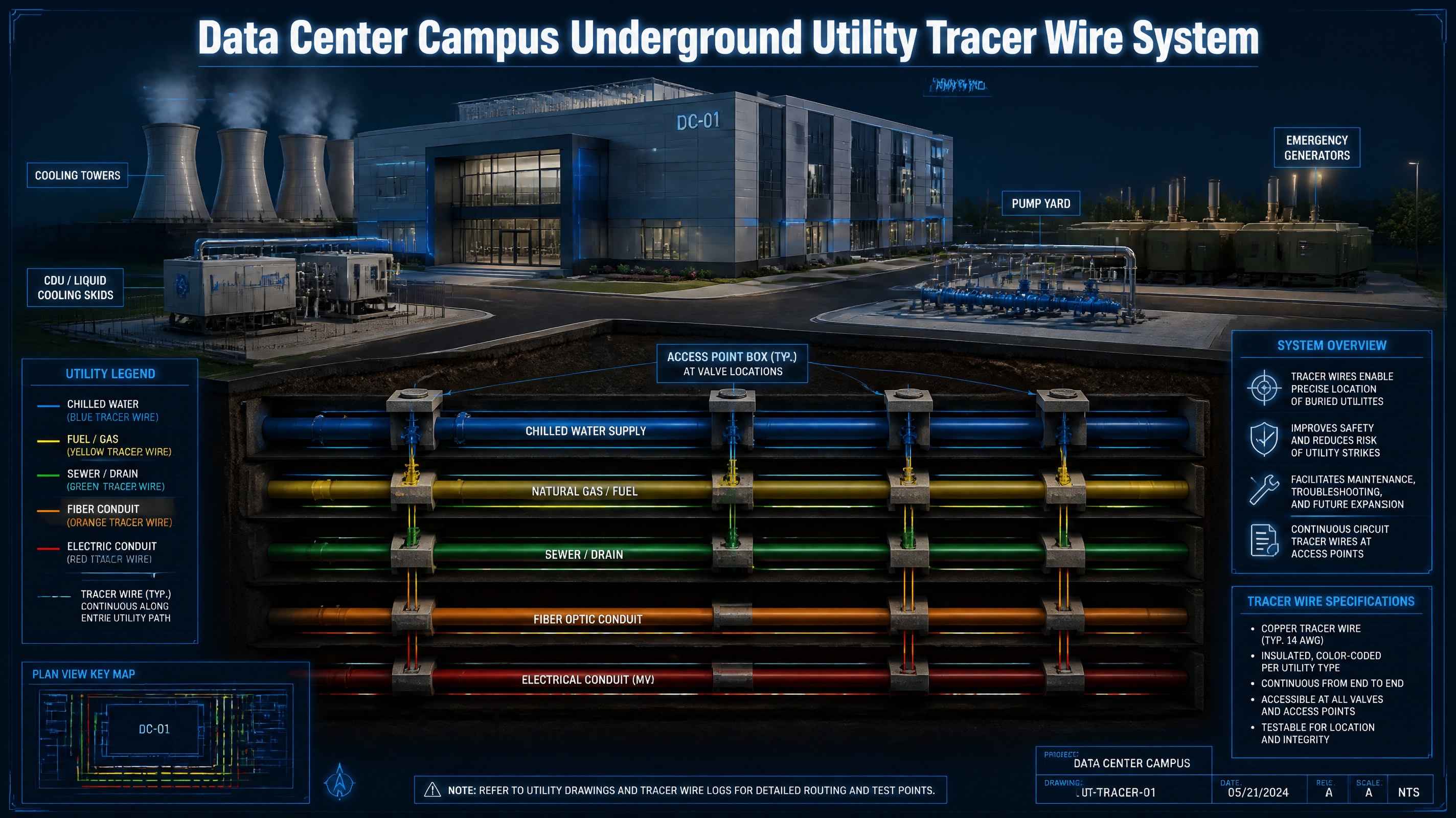
A tracer wire (also called locate wire) is a continuous, energizable conductor installed alongside underground non-metallic pipe to provide an electromagnetic signal path for future locating equipment. It is not a power wire, not a communication cable, and not a leak detection cable. Its singular purpose: make the buried, non-conductive pipe findable by the next crew — years from now.
In a data center campus, this translates directly into the chilled water mains, cooling water loops, glycol supply and return lines, fire water ring mains, fuel lines, communication duct banks, and electrical conduit duct banks that run underground across the site — all of which are increasingly made from non-metallic pipe materials chosen for corrosion resistance.
Tracer Wire vs. Related Cable Types: Critical Distinctions
| Cable Type | Primary Function | Data Center Location | What It Cannot Do |
|---|---|---|---|
| Tracer Wire / Locate Wire | Locate underground / concealed non-metallic pipe routing | Underground CHW, glycol, fire water, fuel, drain, communication & electrical conduit | Cannot detect leaks. Cannot carry power or data signals. |
| Leak Detection Cable | Detect water or conductive liquid at the point of leak | CDU secondary side, rack manifolds, raised floor, valve groups, pump rooms | Cannot locate buried pipe routing. Not a tracer wire substitute. |
| Detectable Warning Tape | Shallow burial warning + limited electromagnetic assist | Installed above pipe in backfill zone; roadways and landscaped areas | Not a standalone locating system for deep burial or complex routing. |
Why Data Centers Have Higher Tracer Wire Stakes Than Ordinary Buildings
Modern hyperscale and colocation data centers are built as multi-phase campus projects. The site may have hundreds of thousands of square feet of raised-floor data hall, multiple mechanical buildings, cooling towers, pump yards, CDU farms, outdoor liquid cooling skids, emergency generator pads, fuel oil storage, and perimeter security infrastructure — all served by a dense web of underground utilities.
| Data Center Site Characteristic | Impact on Tracer Wire Requirement |
|---|---|
| Campus-scale underground utility density | Chilled water, fire water, storm/sanitary sewer, fuel, electrical duct bank, and communication duct bank all cross-run underground. Phase-2 and Phase-3 expansion excavations routinely cut through Phase-1 utilities. |
| AI liquid cooling upgrades | Direct-to-chip and immersion cooling systems require outdoor CDU skids connected to the data hall by buried HDPE or CPVC glycol and chilled water pipes — non-metallic, non-locatable without tracer wire. |
| Phased delivery & multi-year expansion | Phase-1 underground utilities installed without a locating system become a liability when Phase-2 civil/MEP excavation begins 2–5 years later with different crews, different subcontractors, and degraded as-built documentation. |
| Extreme downtime cost | A struck chilled water main, fire service line, or fuel delivery pipe is not a routine repair. It may cause immediate data hall shutdown, fire suppression failure, or a safety incident. A 1-hour outage at a hyperscale facility can cost seven figures. |
| Private campus, outside 811 jurisdiction | Many data center campus utilities are owner-private facilities not registered in the 811 one-call system. The owner's internal tracer wire access records and as-built maps become the only locating source. |
Full-Campus Application Scenarios: Priority Classification
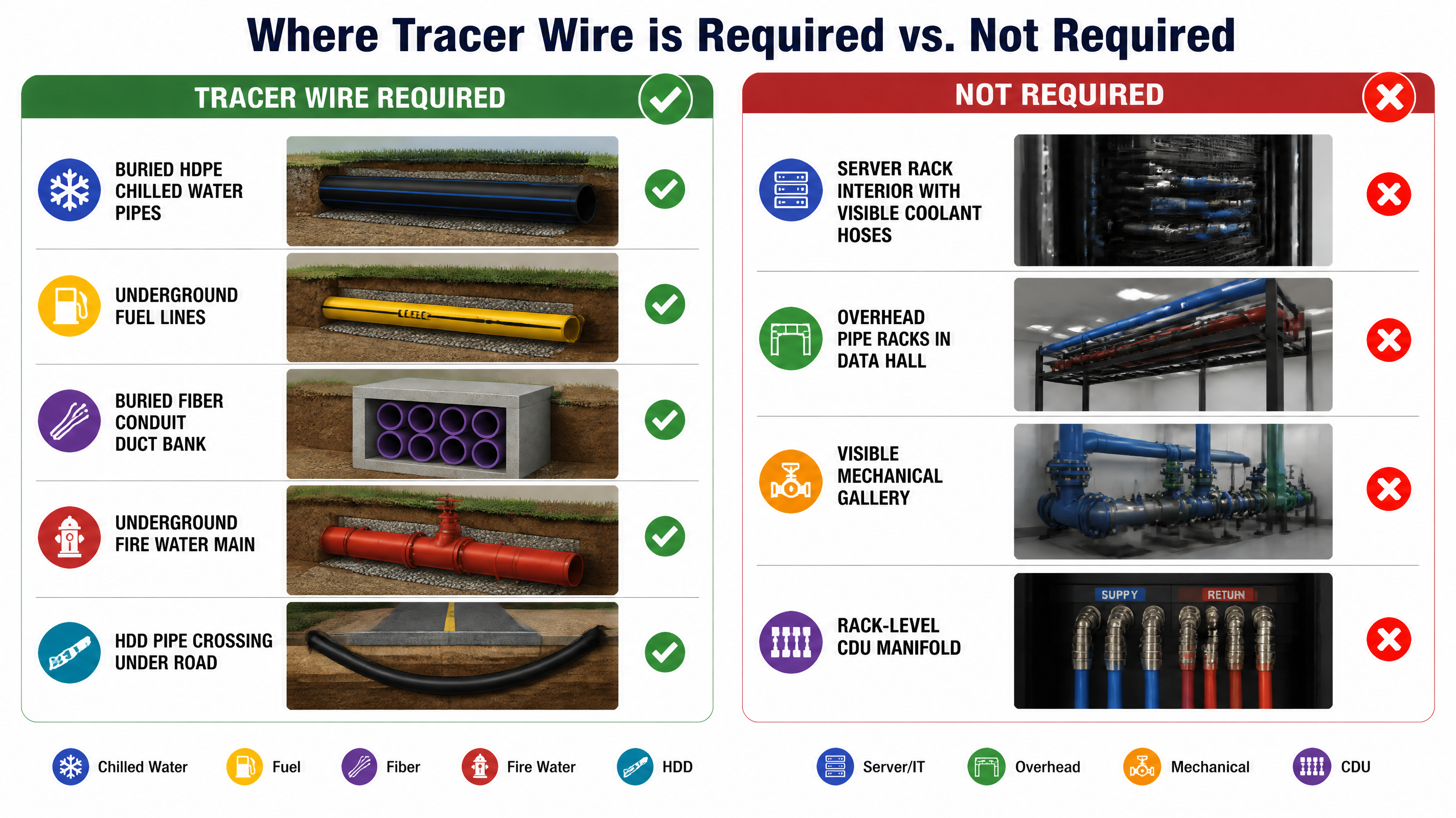
Not every pipe in a data center needs tracer wire. The table below provides a complete priority matrix based on underground vs. visible routing, non-metallic pipe material, excavation frequency, and consequence of misidentification.
| Priority | Application Scenario | Why Tracer Wire Is Needed | APWA Color | Demand Level |
|---|---|---|---|---|
| Class A | Underground CHW / CW / glycol supply & return from central plant, cooling tower, pump yard to data hall | HDPE/PVC/CPVC non-metallic pipe; post-construction road cuts and expansion excavations cannot locate pipe without tracer wire | Blue | 🔴 Critical |
| Class A | Outdoor CDU / liquid cooling module to building entry — underground glycol or cooling water | AI liquid cooling pushes outdoor CDU and container-format cooling skids that connect to data halls via buried non-metallic fluid lines | Blue / project code | 🔴 Critical |
| Class A | Underground fire water ring main, hydrant laterals, sprinkler service, fire pump yard connections | A struck fire service line disables fire suppression for the entire building sector. Hydrant and valve locations must be independently locatable. | Blue — print: FIRE WATER | 🔴 Critical |
| Class A | Diesel fuel / natural gas / generator fuel delivery, underground storage tank connections | Backup power is the data center's last line of defense. Fuel line strikes carry explosion, spill, and regulatory risk in addition to downtime. | Yellow | 🔴 Critical |
| Class A | Communication fiber duct bank, carrier entrance conduit, campus security / alarm / signal conduit | Non-metallic conduit provides no electromagnetic signature; orange tracer wire is the sole locating path for buried fiber and signal infrastructure | Orange | 🔴 High |
| Class A | Electrical power duct bank, substation control conduit, site lighting conduit | Non-metallic electrical conduit requires an independent locating conductor; a struck live HV conduit is a lethal event | Red | 🔴 High |
| Class B | Storm / sanitary sewer, floor drain, condensate drain, equipment discharge, double-containment drain | Plastic drain lines in deep trenches are unlocatable; damage causes flooding, contamination, or regulatory discharge violations | Green | 🟡 High |
| Class B | Domestic / process / RO-DI / make-up water, humidification supply | Multiple water system branches with non-metallic underground routes serving data hall HVAC systems and cooling water make-up | Blue / project code | 🟡 Medium-High |
| Class B | Reclaimed water, irrigation, cooling tower blowdown, landscaping supply | Campus green infrastructure cross-runs with primary utilities; misidentification can contaminate potable or fire water systems | Purple | 🟡 Medium-High |
| Class C | Overhead pipe racks in data hall, visible CDU manifolds, rack-level direct-to-chip coolant hoses | Visible, labeled, BIM-managed, accessible — leak detection and valve tagging are the priority here, not underground locating | — | 🟢 Low / by project |
Liquid-Cooled Data Centers: Where Tracer Wire Actually Goes
The industry shift to AI inference infrastructure has accelerated adoption of direct-to-chip and rear-door liquid cooling. This creates a common misconception: "our data center is liquid-cooled, so we need tracer wire everywhere in the cooling system." The reality is far more targeted.
| Cooling Chain Location | Typical Pipe Type | Tracer Wire Required? | Primary Cable Need |
|---|---|---|---|
| Rack / server interior — cold plate, quick-disconnect, micro-bore coolant hoses | Flexible tubing, copper or SS fittings | No | Leak detection sensor, flow/pressure monitoring, temperature sensors |
| Row manifold / CDU secondary — rack manifold, CDU secondary side, valve groups | Copper, SS, or cross-linked PE — all visible | No (unless buried/concealed) | Point-type water intrusion sensor, BMS integration, zone isolation valve |
| CDU to building entry — supply/return, glycol, discharge piping | HDPE, CPVC, insulated carbon steel — often buried | Yes — strongly required | Tracer wire + detectable warning tape + access points + leak detection in valve vault |
| Central Utility Plant to data hall — CHW/CW/HHW/condenser water/glycol mains | HDPE, pre-insulated HDPE, CPVC — underground | Yes — critical requirement | Tracer wire system: continuous conductor + access boxes + as-built + locating test |
| Cooling tower / dry cooler / pump yard — tower fill, chemical dosing, blowdown, make-up | PVC, HDPE, CPVC — mixed above and below ground | Yes for underground segments | Tracer wire + color-coded jackets to separate CHW, fire water, reclaimed water routes |
Typical Liquid Cooling Tracer Wire Coverage Path
The path below shows exactly which segments require active tracer wire coverage in a typical AI data center liquid cooling deployment:
Recommended: 3–5 min overview of CDU-to-building entry tracer wire installation.
APWA Color Code System — Data Center Application
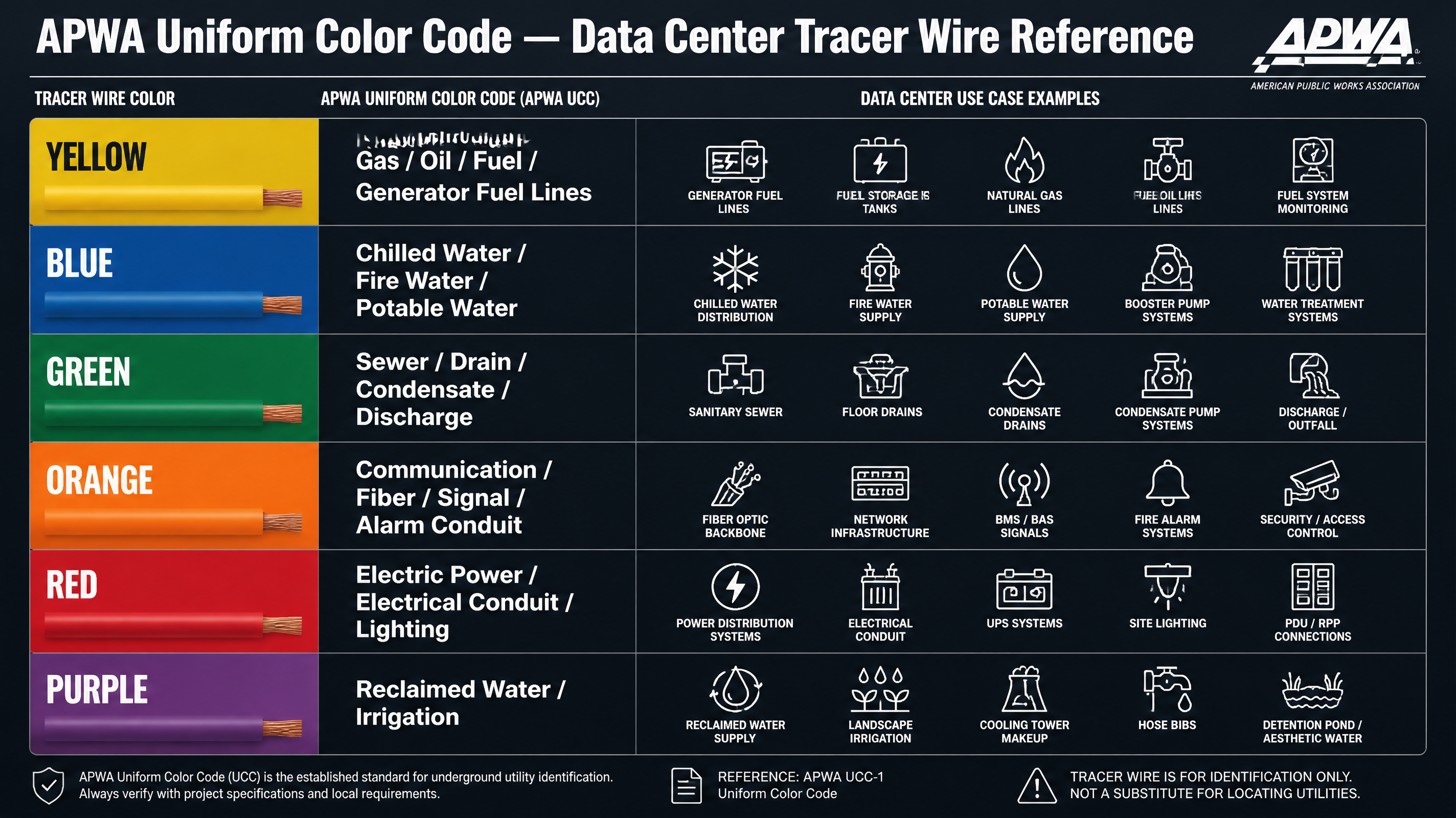
The APWA Uniform Color Code is the standard field identification system for underground utilities across North America. In a data center campus, correct color discipline is not optional — a locating crew that misreads a yellow line as blue could shut down fuel delivery instead of isolating a cooling water leak.
| Color | APWA Utility Category | Data Center Specific Use | Recommended Print Legend |
|---|---|---|---|
| Blue | Potable Water | Chilled water, fire water, domestic / make-up water, CHW/HHW mains | TRACER WIRE – CHILLED WATER / FIRE WATER – DIRECT BURIAL |
| Yellow | Gas / Oil / Steam / Petroleum | Natural gas, diesel fuel, generator fuel delivery, underground fuel storage connections | TRACER WIRE – GAS / DIESEL FUEL – DIRECT BURIAL |
| Green | Sewers & Drain Lines | Storm / sanitary sewer, condensate drain, cooling tower blowdown, RO/DI discharge | TRACER WIRE – SEWER / DRAIN – DIRECT BURIAL |
| Orange | Communication / Alarm / Signal | Fiber optic duct bank, carrier entrance conduit, CCTV / door access / alarm conduit | TRACER WIRE – COMMUNICATION CONDUIT |
| Red | Electric Power / Conduit | Electrical power duct bank, site lighting conduit, substation control conduit | TRACER WIRE – ELECTRIC CONDUIT – DIRECT BURIAL |
| Purple | Reclaimed Water / Irrigation | Reclaimed water, site irrigation, non-potable water distribution | TRACER WIRE – RECLAIMED / IRRIGATION WATER |
Engineering Requirements: Tracer Wire Is a System, Not a Wire
The most common tracer wire failure mode on data center projects is not a bad conductor — it is an incomplete system. Tracer wire buried without accessible test points, waterproof splices, or a continuity test record is the same as no tracer wire at all when an excavator hits paydirt three years later.
| Requirement Category | Engineering Standard | Non-Compliant Practice |
|---|---|---|
| Electrical Continuity | Unbroken conductive path from end to end; tees, crosses, and all laterals electrically connected and documented | Separate wire segments buried in each trench without connecting at junctions; mid-run breaks left untested |
| Access Points | Terminal access at every valve box, hydrant, manhole, building entry, and long-run intervals ≤500 ft per industry practice | Wire end buried in soil; signal only injectable from one end; no intermediate access on 2,000 ft run |
| Direct-Burial Insulation | HDPE or HMWPE jacket rated for direct burial; resistant to moisture, soil chemistry, rodents, and installation abrasion | THHN, bare copper, standard PVC control wire, or indoor-rated wire installed underground |
| Mechanical Strength | Open trench: 14 AWG solid copper is the preferred VOLTIC STONE recommendation for direct-burial campus runs; 12 AWG can be reserved for owner-specified heavier-gauge projects. HDD / pipe bursting / road crossing: HS or EHS copper-clad steel (CCS) per ASTM B1010 or project specification | The right 14 AWG solid copper on open-trench direct-burial runs gives data center buyers a balanced advantage: true-gauge copper conductivity, easier handling, broader color SKU coverage, and efficient stocking. |
| Waterproof Splicing | All splices use direct-burial waterproof connectors (gel-filled, heat-shrink with sealant, or equivalent). Minimize splice count. | Wire nuts, electrical tape, or bare twist joints; splice abandoned in saturated soil |
| Color & Print Legend | Jacket color matches APWA or owner color code; factory-printed legend includes utility type, AWG, conductor material, DIRECT BURIAL, lot number | One roll of yellow wire used for all utilities; color assigned by memory; no print legend |
| Grounding & Termination | Far end terminated per system design using grounding anode, ground rod, or manufacturer-specified method to form a locatable signal loop | Far end connected to rebar, building ground, or metal conduit — creates stray signal, loop interference, and false locate readings |
| Test & As-Built | Pre-backfill continuity test; post-backfill locate test; access point register; as-built with GPS coordinates, depth, pipe diameter, wire gauge, and color | Construction photos only; no field test; no as-built record; future locating relies on institutional memory |
Installation Methods: Open Trench vs. HDD / Directional Drilling
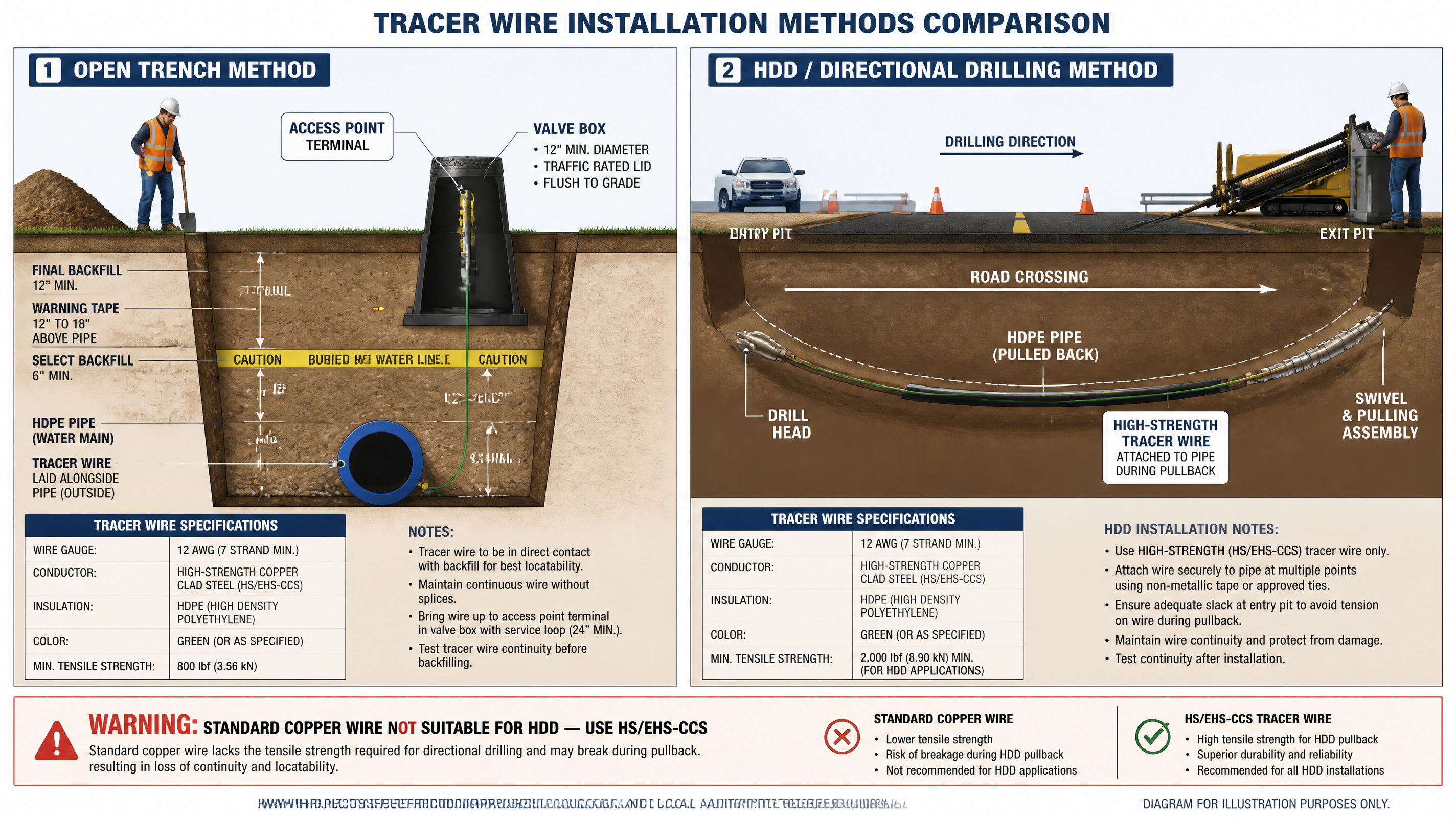
Data center campus utilities use two primary installation methods. The choice of installation method directly determines which tracer wire specification is acceptable — a mistake here means a broken wire that can never be located after backfill.
Open Trench: Step-by-Step Field Sequence
- Excavate trench to pipe design depth; lay pipe on bedding material per specification.
- Position tracer wire alongside pipe — typically at the 10 o'clock or 2 o'clock position per project spec; maintain continuity at all tees, crosses, laterals, and valves.
- At every valve box, hydrant lateral, manhole, and building entry: loop wire out and terminate to an access terminal inside the box — do not leave a buried loose end.
- Install detectable warning tape 12–18 inches above pipe in the initial backfill layer before completing fill.
- Perform continuity test (Megger or dedicated tracer wire tester) before final backfill. Reject if open circuit or high resistance detected.
- Perform locate test with signal transmitter from each access point; compare locate line with pipe design drawing; record depth, GPS coordinates, and signal strength at each access point.
- Submit as-built with: access point numbering, route GPS, depth at key points, wire gauge, jacket color, splice locations, and test results.
HDD / Road Crossing: Critical Differences
- Use 14 AWG solid copper for standard open-trench direct-burial runs; for HDD, road boring, or pipe bursting, move to HS-CCS (#12 AWG, 30 mil HDPE) or EHS-CCS (#10 AWG, 45 mil HDPE) per ASTM B1010.
- Attach tracer wire to the pipe per the HDD contractor's procedure before initiating the pull-back; confirm wire will not wrap or tangle around pipe joints during reaming.
- Immediately after pull-in is complete: perform continuity test at both ends before the crew demobilizes. A broken wire on an HDD crossing cannot be repaired without re-drilling.
- Set access terminals at both entry and exit pits. For crossing lengths over 500 ft, consult owner specification for intermediate test requirements.
- Mark both pits on as-built; record crossing depth, angle, wire gauge, and continuity test result with the drill rig operator's sign-off.
Access Point System: The Feature Most Projects Get Wrong
A tracer wire without accessible test points is functionally useless three years after installation. The access point system — where the wire surfaces, how it is terminated, and how it is documented — is what separates a locatable utility from an expensive buried copper wire that no one can use.
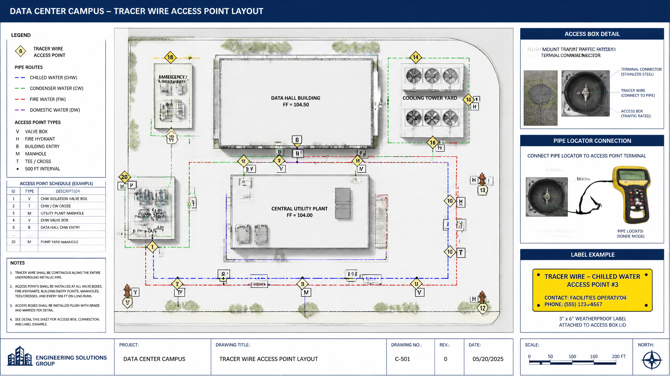
| Access Point Location | Why It Must Have a Terminal | Field Engineering Practice |
|---|---|---|
| Valve Box / Valve Vault | Primary signal injection point; future locate crew will use valve box as starting reference for the entire pipe segment | Terminate tracer wire to a labeled access terminal inside box; at tees/crosses each branch wire must be accessible and identified |
| Fire Hydrant / Hydrant Lateral | Fire service laterals must be independently locatable from the hydrant so the main ring can be traced in isolation | Access terminal at grade flange level of hydrant or in adjacent valve box; label: FIRE WATER – TRACER WIRE ACCESS |
| Building Entry / Wall Sleeve | Most frequently excavated zone during building expansion; point where underground transitions to above-grade mechanical | Terminal in entry vault or exterior backflow room; record on as-built with entry depth, pipe diameter, and wire color |
| Manhole / Utility Chamber | Intersection point for multiple utilities; correct identification prevents wrong-utility isolation during maintenance | Each entering utility wire terminated and labeled on separate terminals; do not bundle wires from different utility types |
| Long Run ≥ 500 ft | Signal attenuation, locate accuracy, and fault-location accuracy all degrade with run length. Many utility owner specs require ≤500 ft access spacing. | Install above-grade access box or flush-mount pull box at mid-run; record GPS coordinate and box ID on as-built |
| Pipe Tee / Cross / Lateral | Directional complexity: a locate crew must be able to independently verify each branch direction from the junction | All branches connected and accessible; label each branch direction (e.g., "TO BUILDING A", "TO COOLING TOWER NORTH") |
Commissioning & Acceptance Testing: What Every Data Center Owner Should Require
Tracer wire commissioning is not a contractor checkbox — it is the owner's warranty that the underground utility infrastructure will be locatable for the life of the facility. The following test protocol should be written into every data center site utilities specification.
| Test Item | Method | Acceptance Standard / Deliverable |
|---|---|---|
| Continuity Test | Multimeter or dedicated tracer wire tester: measure resistance end-to-end for each segment and each branch | No open circuit; resistance consistent with wire gauge and length; all branch connections verified |
| Locator Field Test | Inject signal at access terminal; walk the route with pipe/cable locator; mark locate line with flags at regular intervals | Ground-marked locate path within ±12 inches of design route; depth readings consistent with trench log |
| Access Point Inspection | Open each valve box, hydrant vault, manhole, and building entry; inspect terminal condition | Terminal accessible, corrosion-free, labeled, protective cap installed; no bare wire ends buried in soil |
| Splice Inspection | Verify all splices use direct-burial waterproof connectors per specified type; document splice count and location | Zero wire nuts, zero electrical tape wraps, zero bare joints; each splice mapped on as-built |
| Color / Legend Verification | Spot-check jacket samples at each access point against project utility color schedule | Jacket color matches APWA / owner code for each utility type; print legend legible; AWG and DIRECT BURIAL visible |
| As-Built Documentation | GPS-surveyed route, access point register with ID numbers, depth log, test records, photos | Deliverable: CAD or GIS as-built layer + PDF test report + access point schedule, submitted before substantial completion |
Recommended: 2–3 min walkthrough showing valve box terminal connection and locate-path verification.
Wire Specification Guide: Choosing the Right Product for Each Scenario
Not all tracer wire is equal. A data center campus specification may require three different wire types — one for open trench private campus runs, one for municipal or utility-owner-spec chilled water mains, and one for HDD road crossings. The table below maps each scenario to the correct product type.
| Product Type | Data Center Application | Specification | Notes |
|---|---|---|---|
| 14 AWG Solid Copper Direct Burial |
Open trench CHW, fire water, drainage, private campus conduit — primary recommendation | 14/1 solid pure copper; 30 mil HDPE/PE direct-burial insulation; APWA colors; 50/100/250/500/1000 ft options; factory print legend | Best fit for VOLTIC STONE data center buyers: true-gauge copper, easier handling than heavier wire, broad six-color SKU coverage, and efficient purchasing for campus runs |
| 12 AWG Solid Copper Direct Burial |
Owner-specified heavier-gauge open-trench runs where project documents require 12 AWG | 12/1 solid copper; direct-burial insulation; APWA colors; project-specific reel lengths | Use when a municipal or owner spec specifically calls for 12 AWG; otherwise 14 AWG is the more practical standard SKU direction |
| #12 HS-CCS | Municipal-spec water/fire water, longer trench runs referenced by MRWA or utility owner spec | #12 copper-clad steel, High Strength; 30 mil HDPE; APWA colors; break load per ASTM B1010 | Preferred by municipal water/wastewater specs; required by many investor-owned utility interconnects |
| #10 EHS-CCS | HDD road crossings, long-distance water/fuel main pull-ins, critical CHW river/rail crossings | #10 Extra High Strength copper-clad steel; 45 mil HDPE; high break load per ASTM B1010 | Engineered specification product; high value for project procurement channel; specify for all HDD segments |
| Accessory Kit | All data center projects — ensures system completeness | Access boxes, grounding anodes, waterproof direct-bury splice connectors, detectable warning tape, print labels | Selling wire without the system accessories leaves the customer unable to build a compliant locating system |
VOLTIC STONE 14 AWG Tracer Wire Product Line for Data Center Campus Projects


11 Specification Mistakes That Leave Data Center Underground Utilities Unlocatable
These are the most common tracer wire failures observed on real data center campus projects. Each one creates a permanent locating liability.
| Incorrect Specification or Practice | Why It Fails | Correct Approach |
|---|---|---|
| "Tracer wire for all liquid-cooled data center piping" | Rack coolant hoses, CDU manifolds, and visible mechanical gallery pipe do not need tracer wire and cannot use it | Scope tracer wire to underground and concealed non-metallic segments only |
| "Any color tracer wire is acceptable" | A locate crew identifying utilities by color cannot distinguish a fuel line from a chilled water main without APWA color discipline | Specify APWA color code per utility type with factory-printed legend |
| "One wire type for every installation method" | 14 AWG solid copper is a strong choice for standard open-trench direct-burial runs, but HDD pullback changes the mechanical requirement. | Use VOLTIC STONE 14 AWG solid copper for open trench and specify HS-CCS #12 or EHS-CCS #10 per ASTM B1010 for HDD and pipe bursting. |
| "Tracer wire can detect leaks" | Tracer wire is a locate conductor only; it provides no leak detection signal whatsoever | Use dedicated leak detection c able for all rack-level and manifold-level leak detection needs |
| "Just bury the wire and it will be fine" | A wire with no access terminals cannot be connected to a locator; buried wire ends corrode and become permanently inaccessible | Terminate at every valve, hydrant, manhole, building entry, and at ≤500 ft intervals on long runs |
| "Wire nuts are fine for underground splices" | Wire nuts are not sealed; groundwater infiltration causes conductor corrosion and electrical discontinuity within 1–3 years | Use factory direct-burial waterproof connectors (gel-filled or heat-shrink sealed) for every underground splice |
| "Connect the far end to the building ground" | Grounding the far end to building steel or rebar injects stray current into the signal loop and produces false locate readings | Terminate far end with a grounding anode or per manufacturer's locating system design |
| "Skip the post-backfill test — we tested before backfill" | Backfill compaction and settling can break or displace wire; post-backfill locate test is the only proof the system works as-installed | Perform both pre-backfill continuity AND post-backfill locate signal test; document both in commissioning report |
| "No as-built needed — the drawings are good enough" | Design drawings show intent, not as-installed routing; deviations made in the field are invisible 3 years later | GPS-surveyed as-built with access point register, depth log, and test records before project closeout |
| "We'll use THHN wire — it's the same thing" | THHN is rated for dry or damp conduit installations, not direct burial; jacket degrades rapidly in soil | Specify HDPE or HMWPE jacket rated for direct burial per project specification |
| "One wire color for all data center utilities" | In a future maintenance excavation, an operator cannot tell whether a yellow-jacketed line is chilled water, fire water, or fuel if everything is the same color | Implement the full APWA color set; different utilities may share a trench but never share a wire color or print legend |
Engineering Standards & References
Standards, Best Practices, and Technical References Cited in This Guide
- APWA Uniform Color Code — Underground utility identification color standard for North America. apwa.net
- Common Ground Alliance (CGA) Best Practices Manual v21 — Non-conductive underground facilities should provide an electronic locating means; tracer wire is the standard solution. commongroundalliance.com
- ASTM B1010 / B1010M — Standard specification for copper-clad steel (CCS) tracer wire / locating wire for direct burial underground applications. astm.org
- MRWA Trace Wire Specification Guide — #12 CCS, 30 mil HDPE, open trench / HDD / pipe bursting engineering specifications for water and wastewater utilities. mrwa.com
- American Water Tracer Wire Specification 33-05-27 — Access point spacing ≤500 ft, valve box / manhole terminal requirements, and acceptance testing protocol. amwater.com
- TAMU Underground Piping Installations Design Standard — HDPE for potable water, CHW, HHW, sanitary sewer; 45 mil HDPE tracer wire jacket; blue for water, green for sewer color coding. facilities.tamu.edu
- IPEX Data Center Piping and Cooling Solutions — Thermoplastic piping systems for data center cooling, drainage, ventilation, electrical, and fuel delivery. ipexna.com
- Vertiv Direct-to-Chip Cooling Technical Article — Liquid cooling system components: cold plate, CDU, heat exchanger, and facility water interface; basis for distinguishing leak detection scope from tracer wire scope. vertiv.com
- ASHRAE Liquid Cooling White Paper — Emergence and expansion of liquid cooling in mainstream data centers; chilled water and cooling water system architecture background. ashrae.org
Build a Complete Data Center Campus
Tracer Wire System
Solid copper conductors. HDPE direct-burial insulation. APWA color-coded jackets with factory-printed legends. Available in all six utility colors — engineered for campus-scale underground utility locating.
Shop All Tracer Wire → Request Project Quote